Overview
The Verilog parser is a program that extracts information from multi-level combinational logic circuits written in Verilog.
This parser is developed in C, tokenizes a Verilog file, and invokes various callback methods.
The program then generates a BDD (Binary Decision Diagram) from the Verilog netlist.
The information that the parser extracts includes:
- The module name
- The list of instantiations in the module
- The list of inputs
- The list of outputs
- The list of internal wires
- The list of logic gates
Highlights
- Parses structural subset of Verilog-95, Verilog-2001 and Verilog 2005
- Only applies to combinational logic circuits
What is a Verilog parser?
Parsing is the process of analyzing text made of a sequence of tokens to determine its grammatical structure on a given formal grammar.
In computing, a parser is a program that analyses files to identify the parts.
In this application to Verilog, the parser then builds a data structure based on the tokens and keywords in the netlist.
How does a parser work?
The parser traverses the Verilog file line by line and stores all the lines starting with a Verilog keyword such as input, output, wire, reg, XOR, AND etc.
The parser skips comment lines, empty lines, or spaces.
The parser tokenizes the valid lines and extracts all the data
Phase 1: Parsing the netlist into a structure
The Verilog parser parses a Verilog netlist into a ‘circuit’ object.
The circuit contains logic gates, input wires, internal wires, and output wires.
Each logic gate and wire has attributes such as:
- ID number
- Name
- Type
- Number of inputs
- Input(s)
- Number of outputs
- Output(s)
- Output
- Node
struct wire_    {
    int id;		/*Wire ID number*/
    char *name;	/*Name of this wire*/
    char *type; 	/*Type of gate driving this wire*/
    int inputcount;		/*Number of wire inputs*/
    int inputs[LINESIZE];	/*Array of inputs*/
    int outputcount;
    int outputs[LINESIZE];	/*Array of outputs.*/
    bool primary;		/*Primary input flag*/
    DdNode	*BDD;		/* BDD for this wire */
};
typedef struct wire_ *wire;
Phase 2: Build the BDD recursively
Once the circuit structure is created, the program builds a BDD recursively.
Starting from the primary outputs, the program builds a Binary Decision Diagram for each logic gate encountered until the primary inputs are reached using recursion.
The recursion uses the following rules
The recursive case:
- The BDD of a wire is the BDD of the logic gate driving that wire
- The BDD of a logic gate is the result of its logic operation applied to the BDDs of its input variable.
In other words, the BDD results from operation over smaller BDDs.
e.g.:
– The BDD of an AND logic gate is the logical conjunction of the BDDs of its input variables.
– The BDD of an Exclusive-OR logic gate is the exclusive or of the BDDs of its input variables.
– The BDD of an inverter is the inverted BDD of its input variable.
The base case:
If all the inputs of a logic gate are primary inputs, then the BDD is fully created. The recursive function stops.
Note: The binary decision diagram is a canonical representation of a Boolean function.
However, the variable order may differ between two representations of the same function, depending on the variable reordering method used.
The CUDD package
The operations above were performed using the routines provided by CUDD; we built a library of BDDs corresponding to the most common netlist elements.
We can create BDDs for primitive logic gates such as AND, OR, XOR, NOT using routines for conjunction, disjunction, and complement.
Algorithms of linear complexity are already available in CUDD and referred to as Cudd_BDDAnd, Cudd_BDDOr, Cudd_BDDXor, Cudd_BDDNot and can be used to iteratively construct new BDDs from existing ones.
The operation is performed by first creating a unique variable for each gate input, referencing it, then applying the above routine to the inputs.
The functions return a pointer to the resulting BDD if successful. These small BDDs are used as building blocks to compute larger partitions of parallel elements.
Example 1: A logic AND
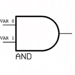
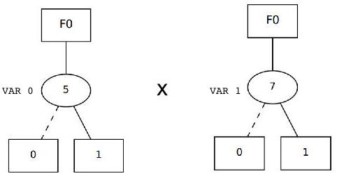
The following example shows a 2-input logic AND gate with inputs. Each of the input variables has a unique node.
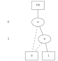
The BDD of an AND logic gate is the logical conjunction of the BDDs of its input variables.
Logic gate for a logic AND
Multiplication of the two input node variables
BDD for a logic AND
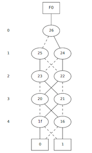
Example 2: xor5.v
The parser builds the BDD of the xor5.v benchmark circuit recursively
BDD for output xor5 of xor5.v
- Number of variables on which the BDD depends: 11
- Number of BDD nodes: 5
xor5
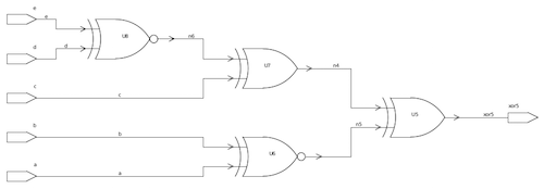
BDD for output xor5 of xor5
Example 3: test1.v
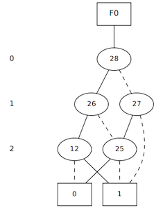
The parser builds the BDD of the test1.v benchmark circuit recursively
BDD for output _o2 of test1.v
- Number of variables on which the BDD depends: 3
- Number of BDD nodes: 7
test1

BDD for output _o2 of test1
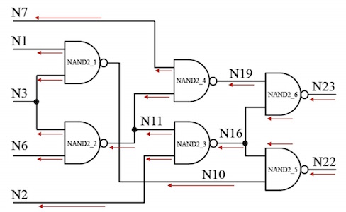
Example 4: c17.v
The parser builds the BDD of the c17.v benchmark circuit recursively
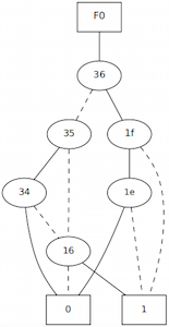
BDD for output N23 of c17.v
- Number of variables on which the BDD depends: 4
- Number of BDD nodes: 8
c17
BDD for output N23 of c17
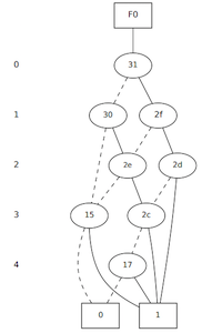
Example 5: majority.v
The parser builds the BDD of the majority.v benchmark circuit recursively
BDD for output o0 of majority.v
- Number of variables on which the BDD depends: 5
- Number of BDD nodes: 10
majority

BDD for output 02 of majority
Example 6: rd53.v
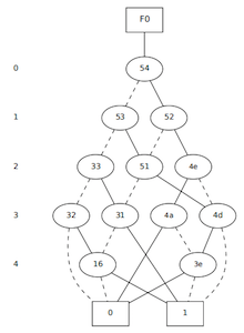
The parser builds the BDD of the rd53.v benchmark circuit recursively
BDD for output o2 of rd53.v
- Number of variables on which the BDD depends: 5
- Number of BDD nodes: 14
rd53
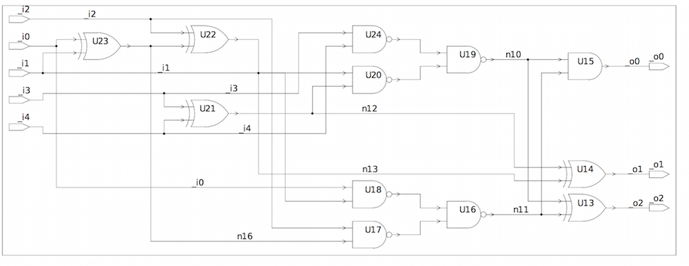
BDD for output o2 of rd53
Example 7: con1.v
The parser builds the BDD of the con1.v benchmark circuit recursively
BDD for output f1 of con1.v
- Number of variables on which the BDD depends: 5
- Number of BDD nodes: 10
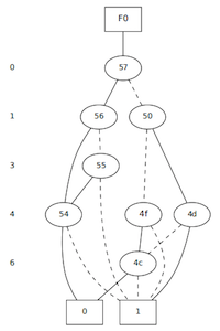
con1
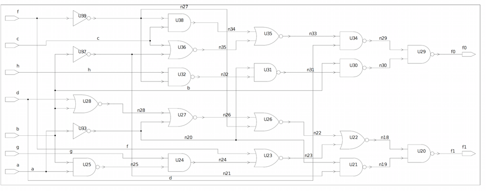
BDD for output f1 of con1
Example 8: rd73.v
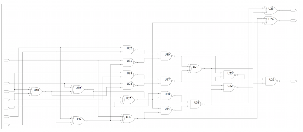
The parser builds the BDD of the rd73.v benchmark circuit recursively
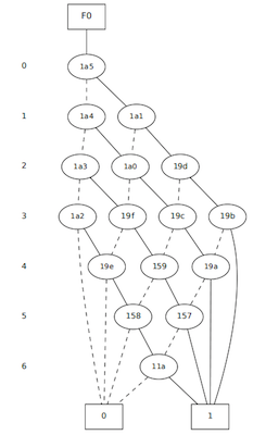
BDD for output _o2 of rd73.v
- Number of variables on which the BDD depends: 7
- Number of BDD nodes: 18
rd73
BDD for output _o2 of rd73
Example 9: c432.v
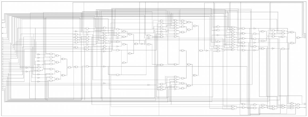
The parser builds the BDD of the c432.v benchmark circuit recursively for all its outputs.
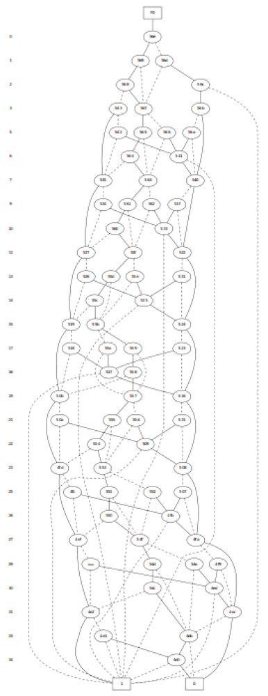
BDD for output N329 of c432.v
The figure below shows the BDD of output N329 of c432.v
- Number of variables on which the BDD depends: 27
- Number of BDD nodes: 75
c432
BDD for output N329 of c432
BDD for output N370 of c432.v
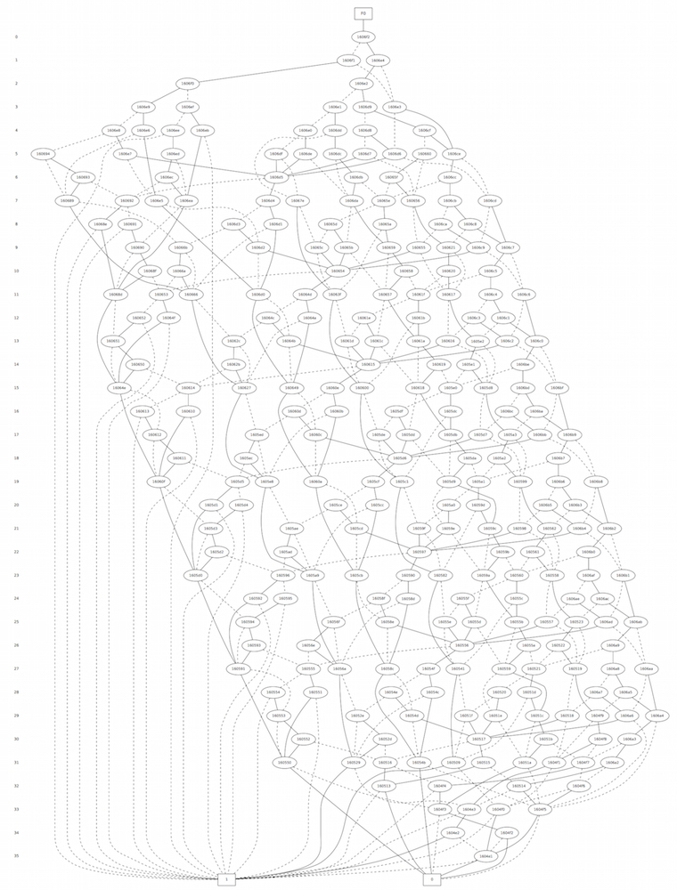
The figure below shows the BDD of output N370 of c432.v
- Number of variables on which the BDD depends: 36
- Number of BDD nodes: 267
c432

BDD for output N370 of c432
Example 10: cm162a.v
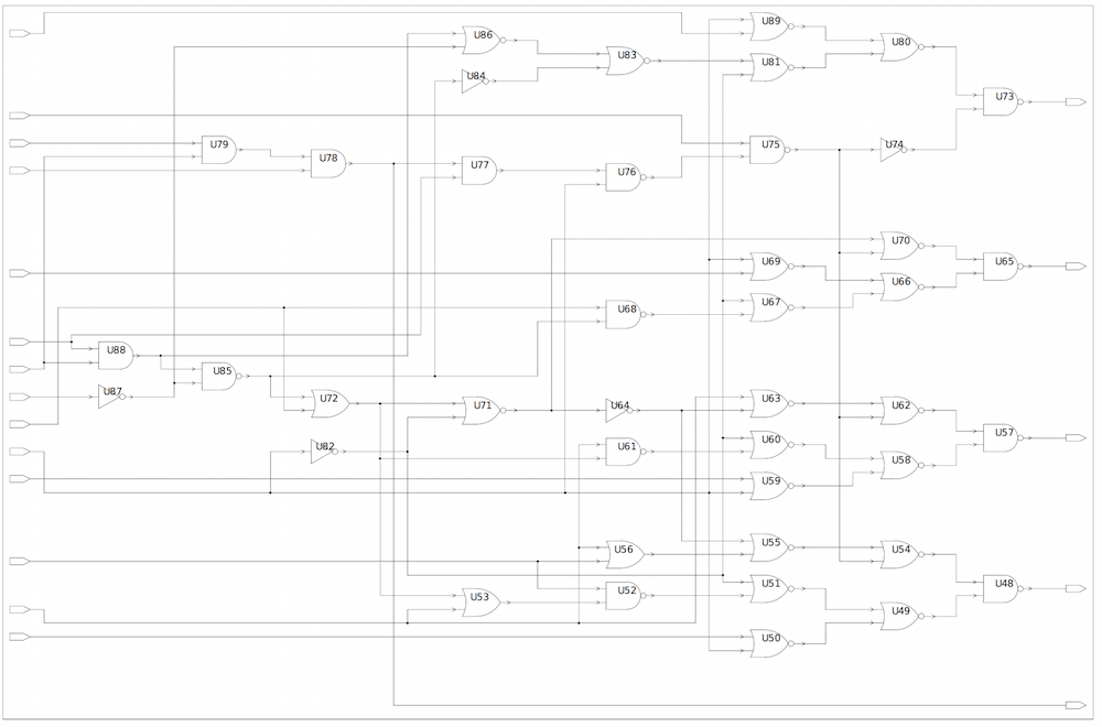
The parser builds the BDD of the cm162a.v benchmark circuit recursively
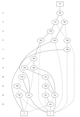
BDD for output r of cm162a.v
- Number of variables on which the BDD depends:11
- Number of BDD nodes: 22
cm162a
BDD for output f1 of cm162a
Summary table
The table below summarizes the characteristics of the above benchmark circuits.
| Benchmark | Number of variables on which the BDD depends | Number of BDD nodes |
| xor5.v | 11 | 5 |
| test1.v | 3 | 7 |
| c17.v | 4 | 8 |
| majority.v | 5 | 10 |
| rd53.v | 5 | 14 |
| con1.v | 5 | 10 |
| rd73.v | 7 | 18 |
| c432.v (Output N329) | 27 | 75 |
| c432.v (Output N370) | 36 | 267 |
| cm162a.v | 11 | 22 |