David Kebo Houngninou (Under the guidance of Prof. Raj Jain)
Abstract:
Since its first commercial deployment by Sprint Nextel Corporation in 2008, femtocell has continued to gain momentum with mobile network operators in America, Asia, and Europe. A large amount of phone calls are placed indoors, and the technology is now deployed for residential and commercial use. Femtocells reduce the load and congestion on macrocell networks by introducing IP as a backhaul for voice and data. This survey first presents the architecture of the femtocell, successful deployments, and applications for residential and commercial use. Next, it discusses wireless protocols, optimization of femtocell coverage, and RF interference. Finally, the text presents the radio technologies used, and authentication mechanisms to identify a mobile unit entering the femtocell network.
Keywords:
Femtocell, Macrocell, Broadband, Indoor signal, Cellular, Spectrum management, UMTS, CDMA, WCDMA, GSM, LTE, Interference, Handover, Mobile network operator, Wireless access point, Radio network controller, Node B, Core Network, Concentrator, Picochip, Qualcomm, Mobility.
See Also:
Table of Contents
- 1. Introduction
- 2. Femtocell architecture
- 3. Optimization of femtocell design
- 4. Challenges and radio technologies used
- 5. Authentication mechanisms
- 6. Summary
- References
- List of Acronyms
1 Introduction
The growing number of cellular network users raises issues about coverage extension in some areas such as rural zones, indoors or underground locations. Mobile network operators now offer femtocell service and plans for both voice and data to residential or commercial customers. In the metric system, Femto (f) is the prefix for a factor of 10 ^ 15. Femtocell are reduced-scale cellular access points typically for indoor use. The cellular gateway is simply connected via broadband and supports a limited number of users for indoor use. It becomes a valuable solution for locations where conventional cellular towers are not installed or locations covered with a weak wireless signal. Femtocell is compatible with any cellular technology, however, vendors are getting more focused on CDMA, 3G UMTS, and the integration of the recent LTE standard.
1.1 What is Femtocell?
Femtocell is a low-power wireless base station for cellular access indoor in areas with limited or no cellular provider. The access point operates in a licensed spectrum and is designed to route mobile phone traffic through a home or corporate IP network. A femtocell is connected to broadband (cable modem or Digital Subscriber Line) and provides complete voice and data service to standard mobile devices such as cell phones, or PDAs that are registered and within a limited range. To ease the installation burden, the units are designed to be user-friendly and plug-and-play. The main features include automatic detection of the ISP, automatic registration, authentication to the cellular core network, self-upgrades, location checks, and transmit power adjustments. Femtocell should not be confused with repeaters generally called “signal boosters” which are only used to improve existing macrocell coverage. The following section provides some details on current femtocell applications.
1.2 Deployments and applications
The commercial use of cellular networks has evolved considerably over the last few years. According to statistics more than 85 percent of Americans have cell phones [Miller09], which drives operators to invest more in technologies such as femtocell. Femtocell is not limited to indoor use only and can be a great option for subway stations, tunnels, and other public areas underground.
Callers usually lose signal from cell towers while driving through tunnels, under bridges, or traveling in subways. These situations can easily be solved by initiating a handover between conventional cellular networks to femtocell access points installed at multiple spots in urban areas. This deployment will also enable travelers to seamlessly surf the internet or make clear quality phone calls while traveling in the subway or through places that used to be without coverage. According to ABI research, the number of worldwide users will jump to 102 million for 32 million access points [Chandrasekhar08]. In terms of deployments in the near future, AT&T is planning on offering its femtocell products in April 2010. The device should be able to carry voice and 3G data [Lee10].
On another hand, compared to other countries, the United States does not allow the use of cell phones on planes. There are still safety concerns about interference with aeronautical systems. Another question is whether or not femtocell is suitable for aircrafts to provide cellular service onboard for a limited number of users.
1.3 Femtocell vs. Voice-over-WiFi
Femtocell and voice-over-WiFi seem to share some features. Since most smartphones are now equipped with WiFi receivers, why are mobile network operators still promoting the use of femtocell? Rather than purchasing equipment and getting a monthly plan from a provider, subscribers may be more inclined to use their existing WiFi network to place calls and send data at no charge. WiFi can be used for voice and is also practical for high data rates over a wide range indoors. However, VoIP must limit the number of simultaneous calls. The system limits the amount of traffic to avoid packet queuing that may cause latency. Since voice calls have real-time requirements, latency in VoIP is not tolerable. The links must be fast enough to route packets before a queue builds up. As an alternative, VoIP also uses Differentiated Services (Diffserv) for voice packets. This Quality of Service (QoS) mechanism gives a higher priority to voice packets during transmission to avoid bottlenecks.
In terms of reliability, femtocell is convenient in the way that it enables an automatic and seamless hard handover between the main cellular network and the home network. Unlike the WiFi solution, the use of a dual-mode phone is not required. Users do not have to worry about losing a connection while leaving femtocell range in their house. The question of seamless roaming is getting quite important as subscribers become more exigent about service quality such as less dropped calls. On another hand, femtocell uses a licensed spectrum strictly allocated by the operator, which makes it less vulnerable to other random radio transmission in the vicinity and guarantees QoS. The table below summarizes some main characteristics of both technologies.
Table 1: Femtocell vs. WiFi features
| Femtocell | WiFi | |
| Spectrum | Licensed (Operator assigned) | Unlicensed |
| Frequency | 1.9 GHz – 2.6 GHz | 2.4 GHz – 5GHz |
| Power | 10 mW – 100 mW | 100 mW – 200 mW |
| Range | 20 m – 30 m | 100 m – 200 m |
| Backhaul | IP network | IP network |
| Data rates | 7.2 Mbps – 14.4 Mbps | 11 Mbps – 54 Mbps |
| Number of active handsets | 1 – 4 | Scalable |
| Cons |
|
Dual-mode handset required |
2. Femtocell architecture
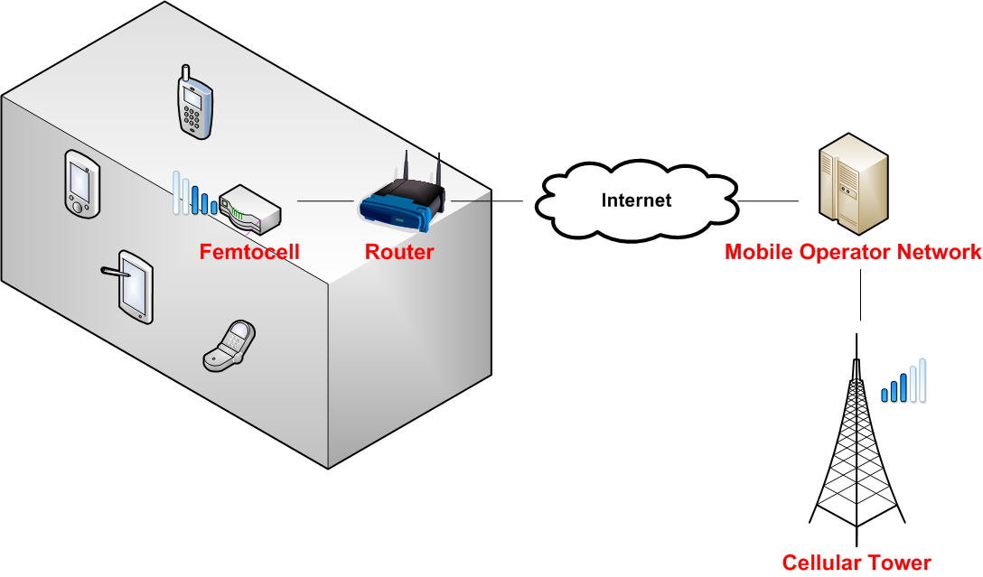
Figure 1: High-Level Femtocell Architecture
From a high-level perspective, the femtocell system includes five parts:
- Femtocell device
- DSL or cable router
- ISP Internet link
- Mobile operator network
- Cellular tower
2.1 Integration of femtocell to the core network
The Universal Mobile Telecommunications System (UMTS) architecture tunnels voice and data traffic between the mobile Core Network (CN) and Femtocell Access Point (FAP) via broadband [Chandrasekhar08]. When a mobile handset is used within the femtocell network, voice or data are encrypted and transmitted from the subscriber’s router to the mobile operator-switching center via IP network. The operator provides a radio network controller that supports multiple femtocell access points. When making a call or sending messages, an Internet Protocol Security (IPsec) tunnel carries encrypted voice and data traffic from the FAP to a Femto Gateway (FGW). The FGW is a security gateway that lies between the core network and the FAP. The traffic to the FGW is made through an interface called IU-H.
Possible configurations:
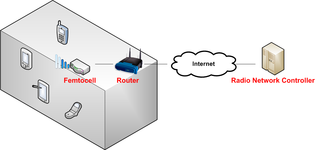
Figure 2: Femtocell access point to radio network controller
In the configuration on Figure 2, the Radio Network Controller RNC is connected to the cellular core network via the Iu interface. The Iu interface carries control information, voice, and data traffic.
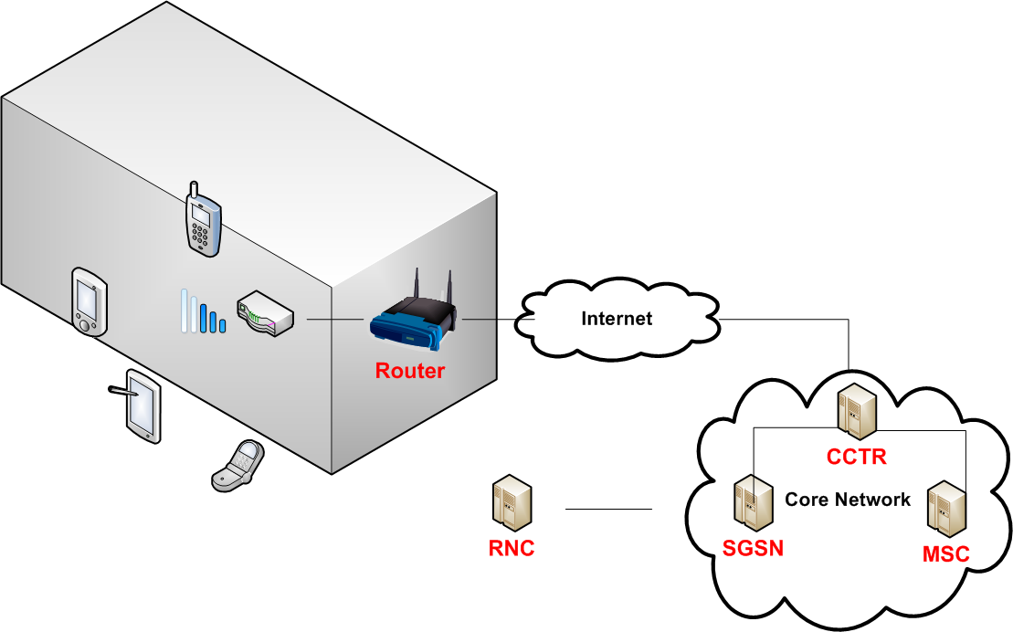
Figure 3: Femtocell access point to concentrator (CCTR)
In the configuration on Figure 3, a concentrator (CCTR) is introduced and is able to manage multiple FAP simultaneously. The SGSN (Serving GPRS Support Node) handles all packet-switched data coming from the concentrator via an Iu-PS interface. The MSC handles all circuit-switched data from the CCTR.
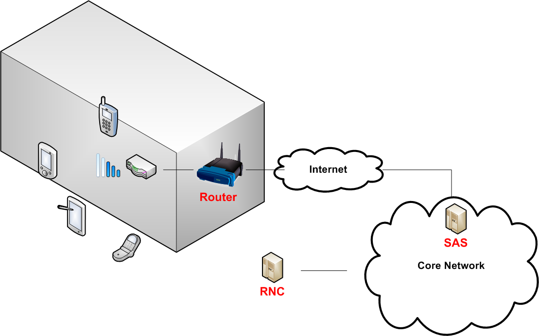
Figure 4: Femtocell access point to SIP application server
In the configuration on figure 4, a SIP application server sits between the FAP and the RNC.
2.2 Handover
Since voice communication has some real-time requirements, femtocell provides a reliable hard handover so that the network transmission is seamless to the user.
- Femtocell – femtocell
- Femtocell – 2G
- Femtocell – 3G
In the transition process from femtocell to macrocell, the mobile station selects the appropriate handover candidate, acquires authentication, and connects to the new access point [Chowdhury09] . Recent handsets are configured to switch automatically to 3G because of the high traffic capacity but fall back to 2G by default when coverage is limited. The transition process from macrocell to femtocell is more complex as the mobile station may have to choose between two or multiple neighboring femtocells. The node B coordinates the handover by provisioning the base station with a list of allowed access points. The process includes several phases such as preparation, signal measurements, authentication, processing, and execution. Figure 5 shows the successive steps between the mobile station, node B, the access point, and the RNC to achieve a handover.
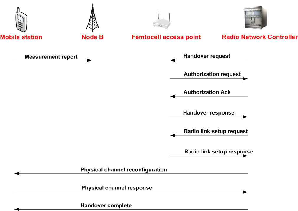
Figure 5: Femtocell handover
2.3 Timing and synchronization
Timing and synchronization are challenges in femtocell deployment. The access point should synchronize with the operator’s core network without manual intervention. It is connected to the core network through an IP backhaul and can only use timing protocols such as IEEE1588 or Network Time Protocol (NTP). Furthermore, the femtocell is installed indoors, and cannot use a GPS antenna for time synchronization. High-precision crystal oscillators can solve the timing problem, but they are often too expensive for consumer-grade devices. As an alternative, Zarlink, a semiconductor company, proposes a recent technology called IEEE1588 Advanced Timing over Packet (ToP). According to a press release for the manufacturer [Zarlink09]: “Advanced Timing over Packet (ToP) technology supports both IEEE1588-2008 and NTPv4 protocols to provide high performance and cost-efficient synchronization for femtocell access points”.
ToP is installed on the core network’s RNC (server side) and on each femtocell access point (client side). When installed on the RNC, ToP works like a time server and provides a time reference to the femtocell access points across the packet network. An internal algorithm keeps track of all the access points’ clock and provides automatic correction when needed. Every packet sent from the RNC has a timestamp containing the time that the packet was launched into the network. In addition, when the RNC receives a packet from a femtocell client it automatically returns an acknowledgment message including the reception time of the packet. The femtocell client uses the acknowledgment message as a reference to adjust its own clock. The figure below illustrates the clock synchronization from the RNC to the femtocells clients.
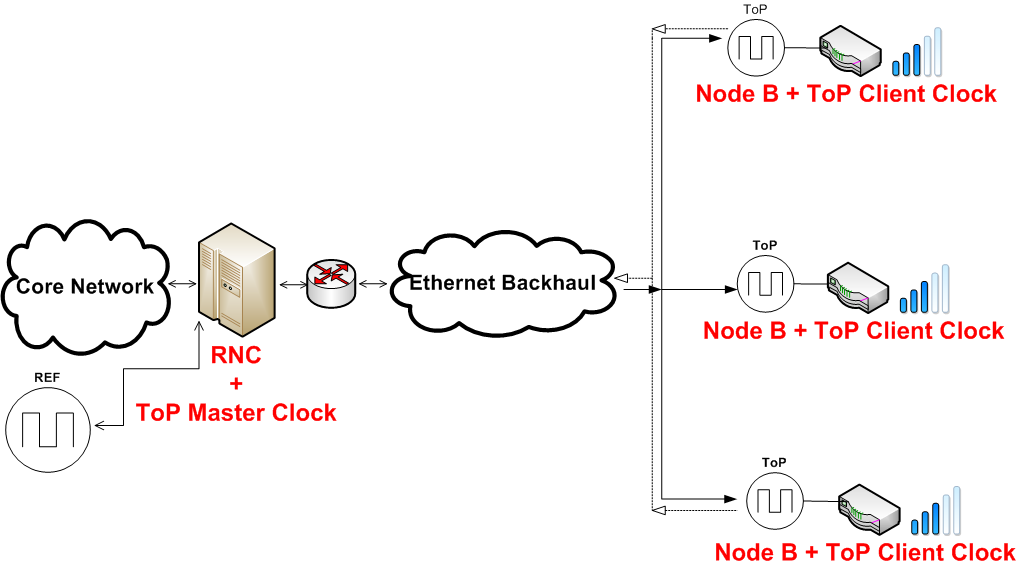
Figure 6: Timing over Packet synchronization
3. Optimization of femtocell design
As a growing technology, femtocell needs some improvement and optimizations in terms of RF interference, coverage, signal strength, and more. Semiconductor companies such as Picochip have already developed solutions for 2G standards (GSM, EDGE, GPRS), 3G standards like WCDMA, TD-SCDMA, cdma2000, and the recent 4G standard LTE. This section addresses schemes to reduce co-channel interference and improve indoor coverage using transmit power adjustments.
3.1 Co-channel interference
This survey addresses the interference issues in the use of femtocells. Various factors such as the number of adjacent units, configuration, or physical locations of the antennas impact performance. Femtocell are very prone to interfere with the macrocell network since they both operate on the same frequency under a licensed spectrum. They can also interfere with each other if multiple units are installed in close proximity. In some cases, conflicting base stations may simultaneously raise transmit power in order to improve signal quality, thereby creating some interference. When a femtocell transmits at high power, it reduces the capacity of the macrocell. A possible solution may use adaptive pilot power control where the femtocell automatically detects surrounding cell signals and adjusts its transmit power accordingly. The power control adapts to variable radio transmission. Once the radio transceiver detects a signal, it compares it to a threshold value and computes a difference. The radio transmit power is either increased or decreased according to the difference. Adaptive pilot power control is not only used to reduce interference but also minimizes power consumption and achieves QoS. The following section presents some ways to improve the signal coverage of femtocells indoor using either an appropriate physical location or an antenna pattern.
3.2 Coverage
In terms of coverage, a unit not installed at a suitable position may cause the signal to leak outside of the premises. It overloads the core network and results in poor service quality in the building. To avoid this situation, the transmit power and the antenna pattern must meet some requirements. According to the auto-configuration scheme defined in [Claussen08], the appropriate femtocell pilot power can be expressed as:
- Lfemto(r): estimated path loss from the femtocell to a device inside radius r.
- Lmacro: path loss between the macrocell and the femtocell.
- Pmacro,pilot: pilot power transmitted by the macrocell and the femtocell.
- Pmacro,pilot: pilot power transmitted by the macrocell and the femtocell.
The equation shows that the base stations must be installed at a strategic location, taking into account the architecture of the building (floor plan, number of floors, walls materials etc…).
As an optimization effort, a multi-element antenna system can also be used [Claussen09]. The femtocell can self-optimize its operation by adjusting its transmit power according to the environment. The multi-element system includes a patch antenna, an inverted-F-antenna (IFA) and a switch. For each antenna, an optimum pilot power is calculated. The patch antenna is flat and integrated easily on top of the main circuit board. The IFA can be printed directly on the main circuit to save space and ease circuitry complexity. As a self-optimization approach, the base station can use a combination of both antennas to transmit signal, cycle through multiple antenna patterns, measure path-loss, and dynamically select the best settings.
3.3 Plug-and-Play deployment
One of the challenges of deployment is to guarantee easy plug-and-play capability and automatic configuration, knowing that most end-users have no networking expertise. The architecture should enable self-configuration to the surrounding environment including the detection of neighboring base stations, transmit power adjustments, or frequency channel allocation. In hardware, the femtocell can be identified using several ways. According to [Claussen-Lester08]: “The femtocell ID provided can be a separate subscriber identity module (SIM) card with configuration information or a preinstalled digital certificate hard-coded in the femtocell”. When plugged in for the first time, an initialization phase consists of sending the unique ID to the operator’s core network for authentication and activation. Using the device ID, the operator performs a location check to ensure that the unit can radiate in an area where the operator owns spectrum usage rights. The location check can be made using geographical coordinates provided by the IP backhaul. Once the device is activated, it receives a set of information from the core network including:
- Frequency for uplink and downlink
- Femtocell scrambling code list
- Cell ID
- Location, routing, and service area codes
- Initial pilot and maximum transmit power
- Macro neighbor search priority list
After receiving the initial parameters, the femtocell scans the radio environment for neighboring base stations and chooses a unique scrambling code. At this point, the access point is initialized and ready to use. To keep track of performance, the core network continuously keeps a log of the information received from the femtocell (Radio frequency measurements, location, firmware versions). The ongoing operating process is described further in section 4.2 for a WCDMA femtocell.
4. Challenges and radio technologies used
This section discusses the deployment challenges of femtocells and two main radio technologies used in femtocell applications: WCDMA and LTE.
4.1 Challenges
Network operators and semiconductor manufacturers face some challenges when deploying femtocells. The challenges include:
Simplified architecture: several femtocell architectures have been designed by manufacturers such as Picochip, Qualcomm, and others for GSM, CDMA, GSM, LTE, or WiMAX. This variety of standards raises some concerns about compatibility, as handsets only support one standard at a time. For instance, a GSM handset cannot operate under a CDMA femtocell and vice-versa. A single industry standard for femtocell may facilitate the integration into the existing core networks.
Access restriction: security protocols must be implemented to limit access to registered subscribers only. A foreign User Equipment (UE) should be denied access to the femtocell network even when it is within the range.
Remote configuration: the operator should keep an activity log of the access point in a database, make frequency adjustments, diagnostic tests and download firmware updates periodically to the access point.
IP backhaul: the access point relies on an IP backhaul that is not controlled the operator. Hardware resets of the router or power outages can cause the femtocell to temporarily lose its connection to the network controller. Next, the IP backhaul lacks of security, QoS and may have a limited bandwidth [Chen10]. In terms of security, the operator must perform a mutual authentication between the Femto Gateway and the access point using a unique ID. In terms of QoS, the operator must guarantee no packet loss, minimal delay, and jitter since femtocell is primarily used for voice applications. In case the call quality drops below a certain threshold, the femtocell should automatically allow a handover to the macrocell network. Finally, in terms of bandwidth limitation, the access points must limit the number of simultaneous users according to the uplink size provided by the ISP.
4.2 WCDMA
Customers with limited technical expertise install the femtocell hotspot. The units are pre-configured to be plug-and-play with minimal settings. The operator is able to control and manage the units remotely. Possible remote operations include firmware updates, frequency or transmit power adjustment, and diagnostic tests. The access point is able to boot up in a network listen mode and scan for available frequencies [Edwards08].
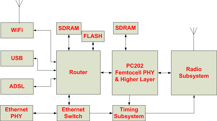
Figure 7: WCDMA Femtocell designed by Picochip
PC202:
Picochip is a major semiconductor manufacturer for wireless applications. The company designs the PC202 processor as the heart of the femtocell. The PC202 includes a DRAM controller, a radio interface [Multi-core10], a 280 MHz ARM9 processor, and a 248-element picoarray. A picoarray is a multi-element array that integrates different types of processors linked by a switch. Hundreds of processors packed on the same chip provide better performance than average DSPs. The objective of the PC202 is the bring performance to access points at a low cost to vendors.
Booting Process:
When the access point boots up several steps occur:
- Synchronize oscillator
- Scan nearby macro networks (2G / 3G) for:
- Frequencies band
- Scrambling codes
- Common channel pilot power
- UMTS Terrestrial Radio Access (UTRA) receives signal strength indicator
- Decode nearby cell information and generate a list. The cell information is available on a broadcast channel.
- Verify the physical location of the access point (country code)
4.3 LTE
Long Term Evolution (LTE) is a recent project of 3GPP designed for higher data rate, low latency, and high spectral efficiency in cellular networks. LTE should cause less interference when deployed between multiple cells and be capable of adjusting to different frequency bands. LTE has a downlink capacity of approximately 100 Mbps and an uplink of 50 Mbps and combines time and frequency division multiplexing. This technology may soon replace 2G and 3G in high-traffic zones such as public places, large businesses, or airports. Even though it supports a high data rate, LTE frequency may result in poor indoor coverage in some areas. In this case, an LTE femtocell can consistently improve the signal of LTE indoors, and unload the macrocell. It is still too early to predict the success of LTE femtocell. Factors such as security, interference, or remote management from the operator need to be considered. Finally, knowing that femtocell uses an IP backhaul, operators will need to verify that the high data rate of LTE does not cause a bottleneck.
5. Authentication mechanisms
Femtocell uses cellular security protocols. As discussed in section I, 2G and 3G networks use different authentication mechanisms. GSM authentication uses EAP-SIM. UMTS and CDMA 2000 use EAP-AKA. Both concepts are developed further below:
5.1 EAP-SIM
3GPP developed the EAP-SIM protocol. Femtocell uses EAP-SIM to establish an IPsec tunnel to reach the network gateway. EAP/SIM stores a secret key on the mobile unit’s SIM card for encryption in the tunnel. The SIM uses a secret key and random number RAND provided by the client to generate a 32-bit response and a 64-bit cipher key [Haverinen06]. EAP/SIM is vulnerable, as it does not offer session independence. The 64-bit cipher strictly depends on the SIM secret key. The cipher combination only changes if the secret key is modified. This allows intruders to breach the system by opening a VPN tunnel and authenticate their mobile unit to the network gateway.
5.2 EAP-AKA
As an alternative to the cipher compromise of EAP/SIM, EAP/AKA is based on the Authentication and Key Agreement mechanism (AKA) for 3rd generation mobile networks specifically. It is more secure as it includes identity privacy support, re-authentication, and generates longer session keys. During the authentication process, the operator produces an authentication vector, based on a secret key and a sequence number. The authentication vector includes the random number RAND, a 128-bit session key for integrity check, and a 128-bit session key for encryption. An identity module verifies the secret key and the sequence number (range), and then generates an authentication result. If the identity verification fails, the process restarts with a new authentication vector.
Both protocols have limitations, but the minimal security requirement for femtocell design should include mutual authentication and session independence [Haverinen06].
6. Summary
By using IP as a backhaul, femtocell reduces the traffic and load on the macrocell network. It also saves operators from the burden of tower deployment and high maintenance costs. Subscribers on the other hand can benefit from a better QoS at a lower rate. This paper covered the applications and deployments of femtocell, a high-level overview of the architecture, and the steps involved in the handover process. It presented a comparison between femtocell and Voice Over IP in terms of QoS and explained the security protocols and authentication mechanisms. One main concern before a wide-scale deployment of femtocell is to avoid RF interference since it has to share the same spectrum with the macrocell. We learned from the survey that features such as adaptive power control, physical location, the number of neighboring cells and antenna pattern are keys to improve femtocell performance. Future research should also focus on matters such as co-channel deployments and MIMO femtocells.
References
[Chandrasekhar08] Chandrasekhar, V. ; Andrews, J. ; Gatherer, A.,“FemToCell networks: a survey”, Communications Magazine IEEE, 2008, Volume 46 Issue:9, Pages 59-67
[Claussen-Lester08] Holger Claussen; Lester T. W. Ho; Louis G. Samuel “An Overview of the Femtocell Concept ”, Bell Labs Technical Journal, 2008, Volume 13 Issue: 1, Pages 221-245
[Chowdhury09] Chowdhury, M.Z.; Won Ryu; Eunjun Rhee; Yeong Min Jang, “Handover between macrocell and femtocell for UMTS based networks”, Advanced Communication Technology. ICACT 2009. 11th International Conference, 2009, Volume 01, Pages 237-241
[Kwanghun09] Kwanghun Han; Youngkyu Choi; Dongmyoung Kim ; Minsoo Na; Sunghyun Choi ; Kiyoung Han, “Optimization of FemToCell network configuration under interference constraints”, Modeling and Optimization in Mobile, Ad Hoc, and Wireless Networks. WiOPT 2009. 7th International Symposium, 2009, Pages 1-7
[Claussen08] Claussen, H.; Ho, L.T.W.; Samuel, L.G., “Self-optimization of coverage for FemToCell deployments”, Wireless Telecommunications Symposium, 2008, Pages 278 – 285
[Claussen09] Claussen, H.; Pivit, F., “Femtocell Coverage Optimization Using Switched Multi-Element Antennas”, Communications IEEE International Conference, 2009, Pages 1-6
[Edwards08] Edwards, J.; “Implementation of network listen modem for WCDMA femtocell”, Cognitive Radio and Software Defined Radios: Technologies and Techniques, 2008, Pages 1-4
[Chen10] Jen Chen; Peter Rauber; Damanjit Singh; Chandru Sundarraman; Peerapol Tinnakornsrisuphap; Mehmet Yavuz; “Femtocells – Architecture & Network Aspects”, Qualcomm, 2010, http://www.qualcomm.com/common/documents/white_papers/Femto_Overview_Rev_C.pdf
[Haverinen06] H. Haverinen, J. Salowey; “Extensible Authentication Protocol Method for Global System for Mobile Communications (GSM) Subscriber Identity Modules (EAP-SIM)”, 2006, http://tools.ietf.org/html/rfc4186
[Lee10] Nicole Lee, “AT & T expands 3G Microcell availability”, 2010, http://www.cnet.com/8301-17918_1-10460190-85.html
[Multi-core10] Products: Multi-core DSP, 2010, http://www.picochip.com/page/75/Multi-core-PC202
[Miller09] Claire Cain Miller, “The Cell Refuseniks, an Ever-Shrinking Club”, 2009, http://www.nytimes.com/2009/10/23/technology/23cell.html
[Zarlink09]Zarlink, “Zarlink Solves Femtocell Synchronization Challenge ”, 2009, http://www.zarlink.com/zarlink/hs/press_releases_21960.htm
List of Acronyms
| IPsec | Internet Protocol Security |
| AP | Access Point |
| BS | Base Station |
| CN | Core Network |
| CCTR | Concentrator |
| FAP | Frequency Access Point |
| FGW | Femto Gateway |
| SIP | Session Initiation Protocol |
| IFA | Inverted-F-Antenna |
| HNB | Home Node B |
| SGSN | Serving GPRS Support Node |
| RNC | Radio Network Controller |
| GSM | Global System for Mobile Communications |
| CDMA | Code Division Multiple Access |
| WCDMA | Wideband Code Division Multiple Access |
| VoIP | Voice-Over-Internet Protocol |
| UMTS | Universal Mobile Telecommunications System |
| 3GPP | 3rd Generation Partnership Project |
| 2G / 3G | Second / Third Generation |
| MIMO | Multiple Input, Multiple Output |
| QoS | Quality of Service |
| RF | Radio Frequency |
| SIM | Subscriber Identity Module |
| SINR | Signal-to-Interference-plus-Noise Ratio |
| UE | User Equipment |
| LTE | Long Term Evolution |
| NTP | Network Time Protocol |
| ToP | Timing over Packet |
Last modified: April 20, 2010.